

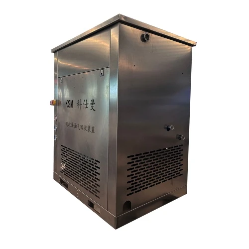

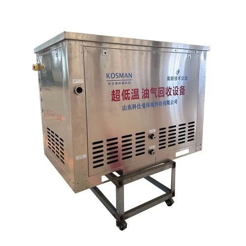
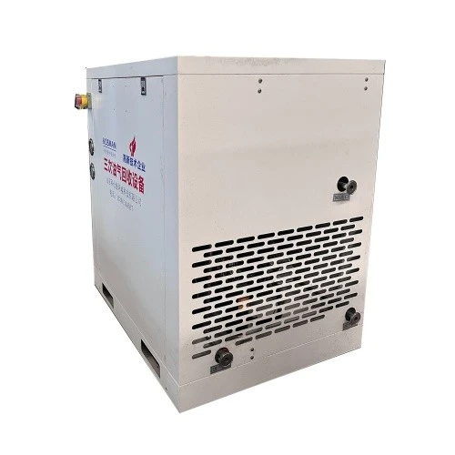
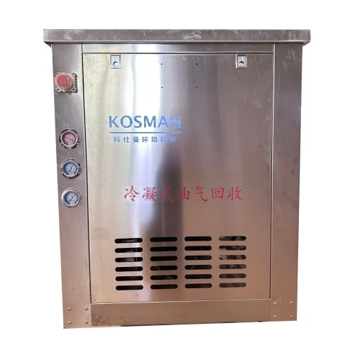
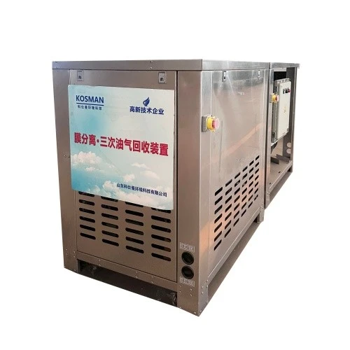
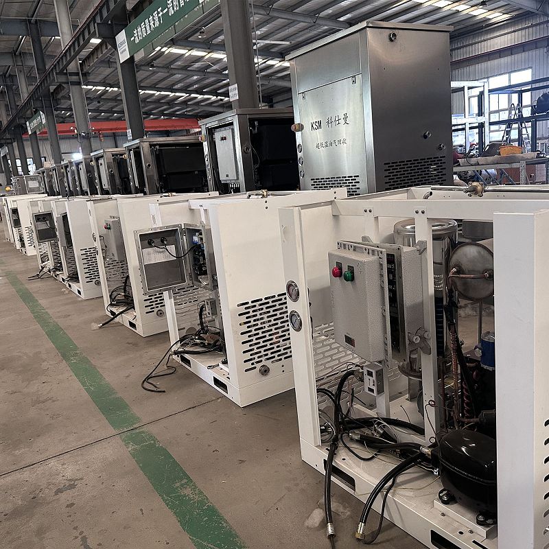
Shandong Kosman Environmental Technology Co., Ltd. is one of the leading manufacturers and suppliers of combined tertiary vapor recovery unit in China. Please feel free to buy premium equipment for sale here and get pricelist from our factory. All customized products are with high quality and low price.
I. Product Overview
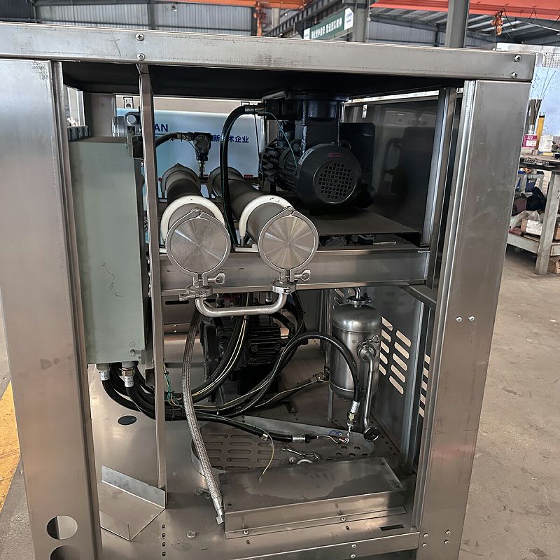
The combined tertiary Vapor recovery unit refers to an environmental protection device that scientifically integrates two or more Vapor recovery technologies (such as condensation, adsorption, and membrane separation) into a single system. It is specifically designed to treat the breathing loss of Vapor in gas station storage tanks caused by diurnal temperature variations and pressure changes, as well as residual Vapor collected and emitted when the gas-liquid ratio of the secondary Vapor recovery system is greater than 1.
With increasingly stringent environmental regulations, a single technology route can no longer achieve a balance between high recovery rate, low operating cost, and stable compliance. Combined processes have become the mainstream solution for tertiary Vapor recovery. The mainstream process adopts a condensation + adsorption combination technology, reducing the potential temperature risks of the adsorption bed through pre-cooling, achieving a non-methane total hydrocarbon concentration in the exhaust gas of 0.36-0.45 mg/m³. The product meets the requirements of the "Emission Standard of Air Pollutants for Gas Stations" (GB 20952-2020) and the "Technical Standard for Vapor Recovery and Treatment Facilities" (GB/T 50759-2022), with a treatment efficiency of ≥95% and an emission concentration of ≤25g/m³. It is a reliable choice for gas stations to achieve a win-win situation of environmental compliance and economic benefits.
II. Technical Principles
2.1 Core Technology Concept
The core design concept of the combined process is "tiered treatment and complementary advantages": firstly, a primary technology (such as condensation) recovers most of the high-concentration Vapor ; then, a secondary technology (such as adsorption) deeply purifies the remaining low-concentration exhaust gas, ultimately achieving the dual goals of high recovery rate and ultra-low emissions. Each individual technology has its applicable scope and limitations; the combined process, through scientific matching, fully leverages the advantages of each technology and compensates for its shortcomings.
2.2 Core Process Technology Route
Currently, the main methods for treating tertiary Vapor recovery at gas stations both domestically and internationally include condensation, absorption, adsorption, and membrane separation, as well as their combined processes. The mainstream combined processes in the current market include the following solutions:
|
Combination Schemes |
Process Flow |
Technical Features |
Applicable Scenarios |
|
Condensation + Adsorption |
Condensation and liquefaction of main Vapor → Adsorption deep purification |
Mature and stable, most widely used, best overall cost-performance ratio |
Mainstream tertiary vapor recovery systems at gas stations |
|
Condensation + Membrane Separation |
Compression and condensation liquefaction → Membrane module separation and purification |
Low energy consumption, long lifespan, no adsorbent replacement cost |
Gas stations, small and medium-sized oil depots |
|
Condensation + Membrane + Adsorption |
Condensation → Membrane separation → Adsorption three-stage deep treatment |
Extremely low emissions, advanced technology |
Environmentally strictly controlled areas, high-standard requirements |
|
Absorption + Adsorption |
Absorber pretreatment → Adsorption deep purification |
Large processing capacity, good adaptability |
Oil depots, refining plant loading platforms |
2.3 Condensation + Adsorption Combination – Detailed Process Flow Explanation
The condensation + adsorption combination is currently the most widely used and mature solution. Its process flow is as follows:
The adsorption method utilizes adsorbent materials such as activated carbon to adsorb organic matter in Vapor . After adsorption saturation, the Vapor are separated by vacuum desorption or steam desorption, and finally condensed into liquid oil. The condensation method uses low-temperature cooling to liquefy hydrocarbons in the Vapor , thereby achieving Vapor recovery. When the two methods are used in combination, the Vapor are first condensed to -75℃ (can be cooled in three stages). Alkanes with C3 or higher are basically condensed and recovered, with a recovery rate of 80%-90%. The remaining small amount of alkanes is sent to the adsorption system for adsorption and recovery treatment. Air that meets the standards after adsorption is discharged; a small amount of Vapor after desorption is returned to the system inlet for circulation. The recovery rate can reach over 97%. The refrigeration temperature setting is designed and formulated according to different operating conditions.
2.4 System Composition
The combined Vapor recovery unit mainly consists of the following core components:
|
Component Names |
Functional Description |
|
Refrigeration Unit |
Provides multi-stage refrigeration, achieving step-by-step condensation and liquefaction of Vapor . |
|
Cold Box (Condenser/Evaporator) |
Core component for oil-gas cooling and heat exchange, featuring multi-stage condensation temperature gradients. |
|
Adsorption Tank |
Integrated activated carbon adsorbent for deep adsorption and purification of low-concentration exhaust gases. |
|
Vacuum Pump |
Vacuum desorption and regeneration of saturated activated carbon. |
|
Oil Pump |
Transports the condensed and recovered liquid oil to the storage tank. |
|
Gas-Liquid Separator |
Separates condensate from uncondensed gas, improving recovery purity. |
|
PLC Control System |
Fully automatic control, real-time monitoring of parameters such as temperature, pressure, and emission concentration. |
|
Online Monitoring System |
Real-time monitoring of gas-liquid ratio, system pressure, and airtightness, supporting automatic fault alarms. |
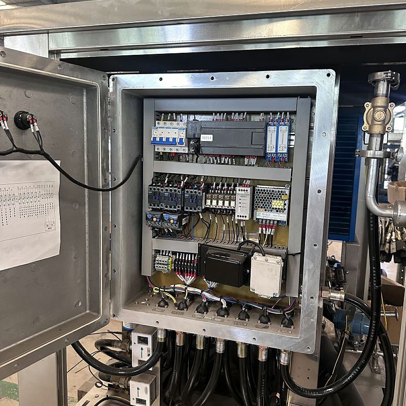
In terms of control, PLC control and frequency conversion regulation technology are used to realize the automatic control of the entire process of Vapor collection, condensation and liquefaction, oil-water separation and condensate oil transportation into storage. The refrigeration unit can realize variable operating condition regulation and economical system operation.
III. Main Combined Process Technical Parameters
3.1 Condensation + Adsorption Combination – Technical Parameters
|
Parameter Items |
Technical Specifications |
|
Processing Capacity |
6~30 Nm³/h (Gas station type); 100-10000 Nm³/h (Oil depot type) |
|
Condensation Temperature |
3℃-40℃-75℃ (Customizable three-stage/four-stage condensation) |
|
Condensation Recovery Rate |
80%-90% (First stage) |
|
Overall Recovery Rate |
≥97% |
|
Emission Concentration |
≤25g/m³ (National standard); ≤10g/m³ (Strictly controlled area standard) |
|
Non-Methane Total Hydrocarbon Tail Gas Concentration |
0.36-0.45mg/m³ (Optimal operating condition) |
|
Explosion-proof Rating |
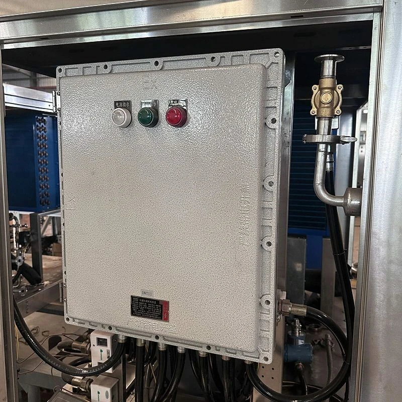
Ex d IIB T4 / Ex de ib mb ⅡC T4 Gb PLC fully automatic control, with online monitoring and remote data transmission functions |
|
Control Method |
Technical Specifications |
3.2 Condensation + Membrane Separation Combination – Technical Parameters
|
Parameter Items |
Technical Specifications |
|
Power Supply |
380V AC Three-phase |
|
Motor Power |
1.5 Kw |
|
Starting Pressure |
+50 Pa |
|
Shutting Pressure |
-130 Pa |
|
Vapor Processing Capacity |
90-100 L/min |
|
Hydrocarbon Content in Emissions |
<25 mg/L |
|
Ambient Temperature |
-20℃~50℃ |
IV. Product Advantages and Features
5.1 Comparison of Mainstream Combination Schemes and Selection Recommendations
|
Solutions: |
Processing capacity: |
Recovery rate |
Key Advantages: |
Technology maturity |
Comprehensive cost |
|
Condensation + Adsorption (combined) |
6-30 m³/h (gas stations) / 100-10000 m³/h (oil depots) |
≥97% |
Mature technology, widest application, balanced cost-effectiveness |
★★★★★ |
★★★ |
|
Condensation + Membrane Separation |
90-100 L/min |
≥95% |
Low operating costs, no adsorbent replacement required |
★★★★ |
★★★★ |
|
Condensation + Membrane Separation + Adsorption |
18 m³/h and above |
≥98-99% |
Extremely low emission concentration, advanced technology |
★★★ |
★★★★★ |
|
Absorption + Adsorption |
100-10000 m³/h |
≥95% |
Largest processing capacity, suitable for oil depots/refineries |
★★★★ |
★★★ |
5.2 Key Selection Factors
Selection should not solely rely on the initial price; the following factors must be comprehensively evaluated:
- Vapor Concentration Fluctuation Range:Concentration is high during loading operations and low during daily respiration losses; the equipment must be adaptable to a wide range of operating conditions.
- Emission Limit Requirements: Some regions enforce stricter local standards; it is necessary to confirm whether the equipment's measured data consistently meets these standards.
- Average Daily Vapor Production:Determined by refueling volume, temperature difference, and storage tank volume, affecting the equipment's processing capacity.
- Site and Power Conditions: Skid-mounted equipment saves space, but the power load and explosion-proof rating must be assessed.
- Operation and Maintenance Capabilities: Adsorption equipment requires regular replacement of the packing material; condensation systems rely on professional refrigeration maintenance.
- Compliance Acceptance:The equipment must provide a third-party testing report and support online monitoring interfaces.
5.3 Selection Recommendations
|
Use Cases |
Daily Sales/Annual Sales |
Recommended Solutions |
Description |
|
Small and medium-sized gas stations |
2000-5000 tons/year |
Condensation + Adsorption (6-8 m³/h) |
Meets national standards, high cost-effectiveness |
|
Large gas stations |
5000-10000 tons/year |
Condensation + Membrane Separation or Condensation + Adsorption (8-12 m³/h) |
Balances high recovery rate with low operating costs |
|
Very large gas stations |
Over 10000 tons/year |
Condensation + Adsorption (12-18 m³/h) |
Sufficient processing capacity, stable operation |
|
Mega gas stations/small oil depots |
Any size |
Condensation + Membrane + Adsorption (Three-stage Deep Treatment) |
Emission concentration ≤10g/m³ |
|
Environmentally strictly controlled areas/high-standard requirements |
Bulk loading |
Absorption + Adsorption (100-10000 m³/h) |
Large processing capacity, suitable for continuous operation |
For the vast majority of gas stations that need to meet national standards (annual sales exceeding 2000 tons), the condensation + adsorption combined process is currently the most comprehensive, widely used, and stable solution. The condensation + membrane separation solution has been successfully applied in some high-standard projects, and its advantages, such as low operating costs and no adsorbent replacement costs, are gaining wider recognition.
VI. Configuration Upgrades and Application Scenarios
6.1 Multi-stage Cooling Upgrade
Four-stage condensation technology is available on the market, with condensation temperatures set from 3℃ to 40℃, 75℃, and 115℃. Adding a fourth stage of deep cooling down to -115℃ to the three-stage condensation system, employing two-stage cascade + self-cascade refrigeration technology (i.e., multi-stage coupled refrigeration), allows for flexible adjustment within the temperature range of -80℃ to -115℃, accommodating both extreme and moderate low-temperature operating modes to cope with varying Vapor compositions and large fluctuations in treatment concentrations, and adapting to increasingly stringent emission standards.
Some continuous production processes employ a dual-path switching process in the low-temperature section-if ice blockage occurs on one side, the system directly switches to the other path for heat exchange and condensation in the cold box, while defrosting is performed on the ice-blocked side to ensure continuous and stable recovery of overflowing gases.
6.2 Expanded Application Areas
Combined Vapor recovery devices have expanded from tertiary Vapor recovery at gas stations to a wider range of applications. They are suitable for Vapor recovery systems in refineries and oil depot tank trucks, associated gas recovery systems in oil fields, separation and recovery of chemical gases such as benzene, and the separation, concentration control, and recovery of mixed gases in chemical production processes. With increasingly stringent environmental standards, the application of combined processes in oil depots, docks, and chemical industrial parks is also continuously expanding.
VII. Installation and Selection
7.1 Installation Conditions
Installation at gas stations that have completed secondary vapor recovery system upgrades.
Equipment foundations must be reserved. Installation must be in a well-ventilated, dedicated area away from heat sources.
A 380V 50Hz three-phase power supply is required; power output depends on the model.
Gas connection: DN40 or DN50 flange connection.
The exhaust pipe outlet should be at least 4 meters above ground level, away from areas with high foot traffic.
7.2 Selection Considerations
Establishment of the model requires an accurate assessment of the gas station's sales volume. An undersized model will result in insufficient recovery rates, while an oversized model will lead to wasted investment. Based on the policy requirement that gas stations with annual sales exceeding 2000 tons must install tertiary vapor recovery devices, a processing capacity of at least 8 m³/h is recommended, conforming to the framework agreement standards of large oil companies such as CNOOC. Local climate conditions should also be considered; in cold regions, anti-freezing measures (such as electric heat tracing, condenser unit anti-freezing protection, etc.) are necessary.
XI. Ordering Information
|
Project |
Contents |
|
Product Name |
Combined tertiary Vapor recovery unit |
|
Optional Process Options |
Condensation + Adsorption / Condensation + Membrane Separation / Condensation + Membrane + Adsorption / Absorption + Adsorption (Customized) |
|
Processing Capacity |
6-30 m³/h (Gas Station Type) / 100-10000 m³/h (Oil Depot Type) / Customized |
|
Condensation Temperature Rating |
-40℃ / -75℃ / -115℃ (Customizable three-stage/four-stage condensation) |
|
Design Standard |
GB/T 50759-2022, GB 20952-2020 |
|
Explosion-proof Rating |
Ex d IIB T4 / Ex de ib mb ⅡC T4 Gb |
|
Equipment Design Life |
≥10 years |
|
Warranty Period |
24 months (Complies with framework agreements of major oil companies, excluding consumables and wear parts) |
|
Production Cycle |
30-60 days (Depending on throughput and process configuration) |
|
Optional Configurations |
Online monitoring system, 4G IoT, cloud management platform, industrial touch screen, data transmission module |
|
After-sales Service |
Technical support, on-site response within 48 hours |
Specific pricing and delivery time are subject to actual inquiry.
Contact Information For more product details, technical solutions, or to obtain a quote, please contact us.
Hot Tags: combined tertiary vapor recovery unit, China combined tertiary vapor recovery unit manufacturers, suppliers, factory