

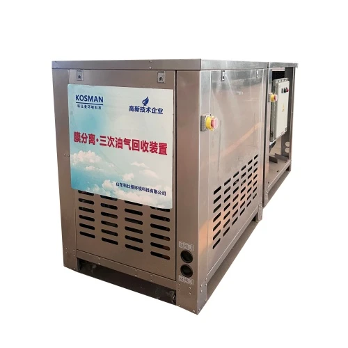

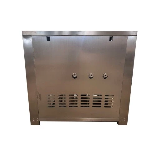
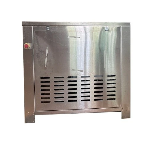
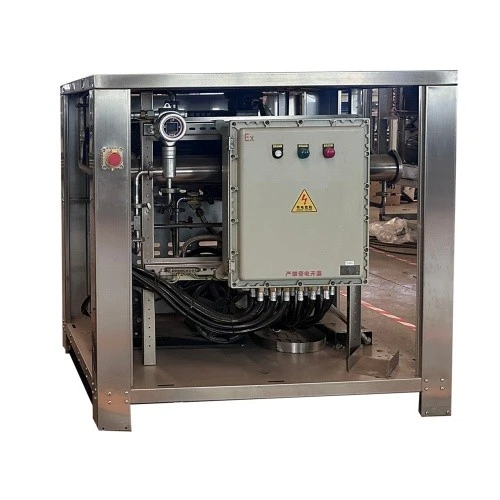
Shandong Kosman Environmental Technology Co., Ltd. is one of the leading manufacturers and suppliers of condensation + membrane separation three-stage vapor recovery unit in China. Please feel free to buy premium equipment for sale here and get pricelist from our factory. All customized products are with high quality and low price.
I. Product Overview
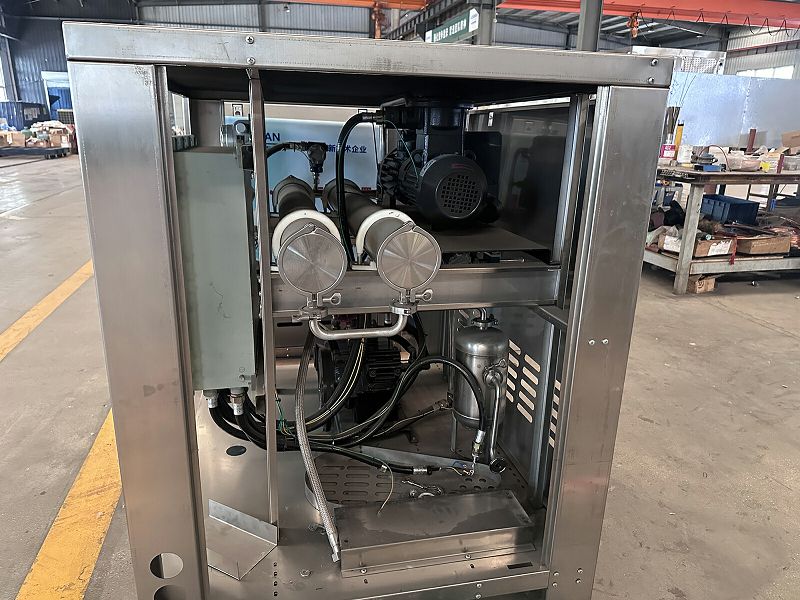
The membrane separation-based tertiary Vapor recovery unit is a high-efficiency, eco-friendly system designed to address Vapor vapor emissions from gas station and oil depot storage tanks. Utilizing a combined process of membrane separation and condensation, the unit exploits the varying permeation rates of different gases through polymer separation membranes to achieve efficient separation of oil/gas vapors from air. The treated exhaust meets emission standards, and the recovered liquid fuel can be directly reused.
The product complies with the *Emission Standard of Air Pollutants for Gas Stations* (GB 20952-2020), featuring a treatment efficiency of ≥95% and an emission concentration of ≤25 g/m³. It represents an optimal choice for gas stations seeking to balance environmental compliance with economic benefits.
II. Working Principle
2.1 Core Technical Principle
Membrane separation technology is based on the solution-diffusion mechanism: when a gas mixture passes through a polymer membrane driven by a pressure differential, hydrocarbon VOC molecules (such as alkanes and aromatic hydrocarbons) and inert gas molecules (nitrogen and oxygen) exhibit significant differences in permeation rates, thereby enabling selective separation.
Two typical membrane separation mechanisms:
|
Membrane Type |
Separation mechanism |
Vapor destination |
Air Destination |
|
Oil/Gas-Permeable |
Preferential adsorption-permeation of VOCs |
Returns to the storage tank via the membrane side |
Captured, directly discharged |
|
Oil/Gas-Retaining |
Preferential permeation of air (glassy membrane) |
Retained and returned to the storage tank |
Through the membrane side, directly discharged |
Glassy-state oil/gas-trapping membrane: At temperatures above the glass transition temperature (Tg), segmental motion occurs within the membrane and free volume increases, which helps enhance the membrane's selectivity for hydrocarbon VOC/air mixtures. Inert gas molecules first dissolve at the membrane surface, diffuse to the opposite side driven by a concentration gradient, and finally desorb.
2.2 Process Flow
The combined membrane separation and condensation process flow is as follows:
Pressure monitoring inside the oil tank (startup condition)
↓
Pressure reaches +50 Pa → System starts
↓
Oil-gas mixture extracted by compressor → Pre-cooled in condenser
↓
┌───────────────────────────────┐
│ Separation via membrane unit │
├───────────────────────────────┤
│ Permeate side: Clean air vented │
│ Retentate side: High-concentration oil-gas returned │
└───────────────────────────────┘
↓
High-concentration oil-gas returned to tank → Naturally liquefies
↓
Pressure inside tank drops below -130 Pa → System stops
2.3 Functions of Core Components
|
Component Name |
Functional Description |
|
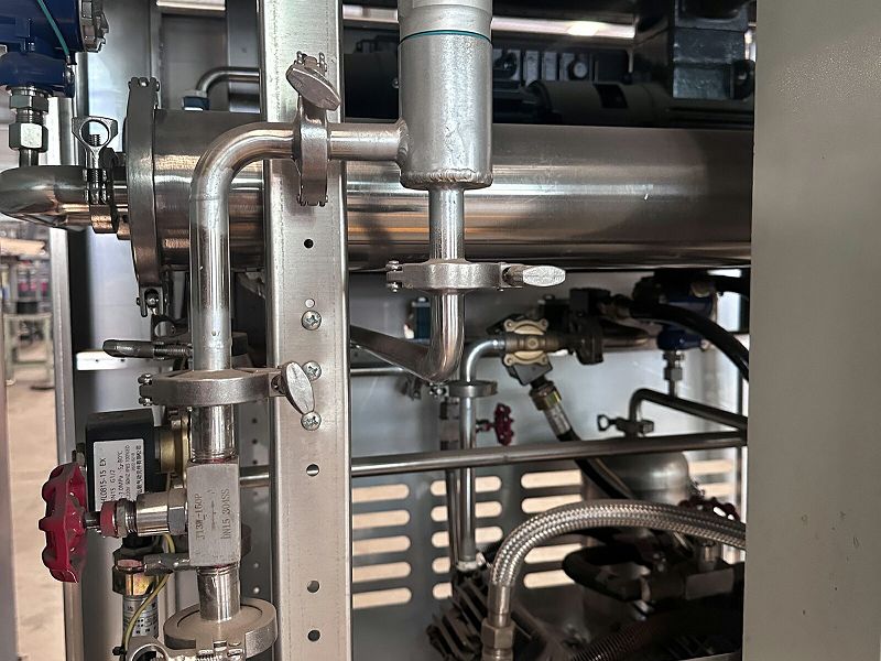
Membrane separation module |
Core separation unit containing a polymer separation membrane to achieve selective separation of oil vapors/air |
|
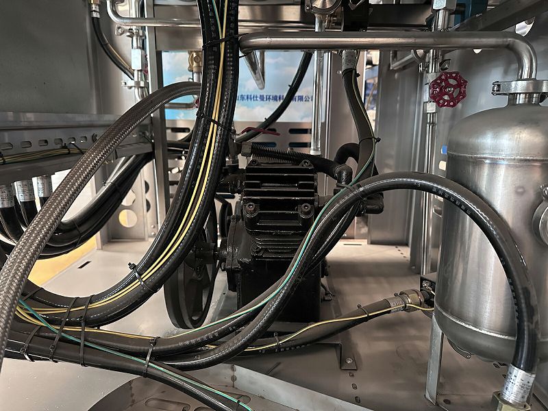
Compressor |
Extracts and pressurizes oil vapors to provide the driving force for membrane separation |
|
Condenser |
Pre-cools oil vapors to liquefy and recover heavy hydrocarbons, thereby reducing the load on the membrane module |
|
Gas-liquid separator |
Separates condensate from uncondensed gas; returns liquid oil to the tank and directs gas to the membrane module |
|
Vacuum pump |
Applies negative pressure to the membrane permeate side to increase the partial pressure difference across the membrane, enhancing separation efficiency |
|
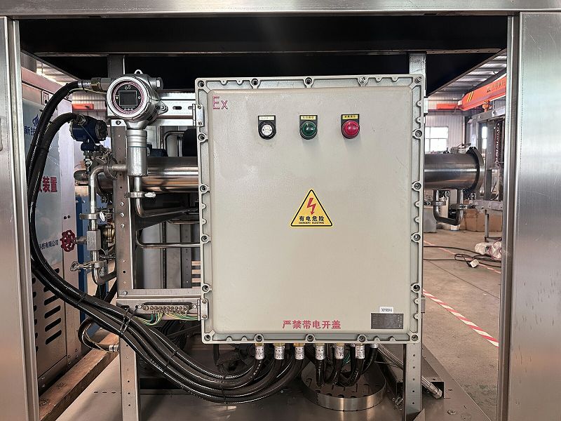
PLC controller |
Fully automated control system monitors parameters such as pressure and temperature in real time, enabling unattended operation |
III. Product Models and Technical Parameters
3.1 List of Standard Models
|
Model |
Processing capability |
Process Combination |
Breakaway pressure |
Shut-off pressure |
Power supply |
Explosion-proof rating |
|
YQM-8 |
8 m³/h |
Air cooling + membrane separation |
+50 Pa |
-130 Pa |
380V/50Hz |
Ex d IIB T4 |
|
YQM-5 |
5 m³/h |
Membrane separation + condensation |
+50 Pa |
-130 Pa |
380V/50Hz |
Ex d IIB T4 |
|
YQM-10 |
10 m³/h |
Membrane separation + condensation |
+50 Pa |
-130 Pa |
380V/50Hz |
Ex d IIB T4 |
|
YQM-30 |
30 m³/h |
Membrane separation + condensation |
+50 Pa |
-130 Pa |
380V/50Hz |
Ex d IIB T4 |
3.2 Detailed Technical Specifications
|
Parameter |
YQM-8 Series |
YQM-5 Series |
YQM-10/30 Series |
|
Gas handling capacity |
8 m³/h |
5 m³/h |
10~30 m³/h |
|
Start-up pressure |
+50 Pa |
+50 Pa |
+50 Pa |
|
Shut-off pressure |
-130 Pa |
-130 Pa |
-130 Pa |
|
Emission concentration |
≤25 mg/L(约25 g/m³) |
≤25 g/m³ |
≤25 g/m³ |
|
Treatment efficiency |
≥95% |
≥95% |
≥95% |
|
Power supply |
380V 50Hz |
380V 50Hz |
380V 50Hz |
|
Motor power |
- |
- |
1.5 kW |
|
Ambient temperature |
- |
-20℃~50℃ |
-20℃~50℃ |
|
Explosion-proof marking |
Ex d IIB T4 |
Ex dibⅡAT3 |
Ex d IIB T4 |
|
Parameter |
YQM-8 Series |
YQM-5 Series |
YQM-10/30 Series |
3.3 Explanation of Performance Indicators
Processing capacity unit: m³/h (standard cubic meters per hour); represents the volume of the oil-gas mixture the equipment can process per hour.
Start-up pressure: The pressure within the oil tank at which the equipment automatically starts.
Shut-down pressure: The pressure within the oil tank at which the equipment automatically stops.
Emission concentration: The content of non-methane total hydrocarbons in the treated exhaust gas; must comply with the national standard of ≤25 g/m³.
IV. Core Advantages and Features
4.1 Advanced Membrane Separation Technology
High-quality imported separation membranes: Uses premium imported membranes that preferentially permeate air; prevents static electricity generation; ensures a safe and reliable treatment process.
High separation efficiency: Under experimental conditions with processing capacities ranging from 2.8 to 4.7 m³/h, the VOC concentration in the residual gas remains consistently below the 25 g/m³ emission limit.
Strong adaptability to pressure fluctuations: Membrane system separation performance is minimally affected by flow rate variations, ensuring compliance across a wide range of processing capacities.
4.2 Advantages of Combined Processes
Synergistic effect of membrane separation and condensation: The condensation process significantly extends the service life of membranes and adsorbents, thereby prolonging the overall lifespan of the unit.
Low-temperature, atmospheric-pressure operation: The entire treatment process operates at low temperatures and atmospheric pressure, ensuring safety and reliability.
Resource recovery: High-concentration Vapor return to the storage tank, where a portion naturally liquefies, generating direct economic benefits.
4.3 Intelligent Control System
Automatic start/stop: Real-time monitoring of tank pressure; automatic operation upon reaching the set value and automatic shutdown when dropping below the cutoff value.
Fully automatic PLC control: One-touch start/stop and round-the-clock automatic operation; no manual supervision required.
Dynamic pressure management: Automatically manages dynamic, minor fluctuations in tank pressure.
Online monitoring: Real-time monitoring of parameters such as inlet pressure, temperature, and flow rate; system operating status is clear at a glance.
4.4 Safe and Reliable Design
Explosion-proof rating: Ex d IIB T4 / Ex dib IIA T3; suitable for flammable and explosive environments.
Closed-loop circulation: Internal circulation design prevents Vapor leakage.
Intrinsically safe: The membrane separation process involves no phase changes or high temperatures, eliminating combustion and explosion risks.
4.5 Energy-saving and Environmental Benefits
Low operating costs: Compact footprint and low operating expenses.
Direct economic benefits: Recovered liquid oil returns to the storage tank, generating significant economic value.
Compliant emissions: Post-treatment tail gas concentration of non-methane total hydrocarbons is <25 mg/L (approx. 25 g/m³), far below national standards.
Carbon emission reduction: Significantly reduces VOC emissions, contributing to the achievement of "Dual Carbon" goals.
V. Application Scenarios
|
Application Areas |
Applications |
Recommended Models |
Application Areas |
|
Gas Stations |
Gas stations with annual sales exceeding 2,000 tons (handling storage tank breathing emissions) |
YQM-8 / YQM-5 |
Gas Stations |
|
Large-scale Gas Stations |
Gas stations with high-volume processing requirements |
YQM-10 / YQM-30 |
Large-scale Gas Stations |
|
Oil Depots |
Vapor treatment for oil depot storage tank farms |
YQM-30 and above |
Oil Depots |
|
Refining and Chemical Enterprises |
Vapor recovery for loading racks and storage tank farms |
Custom models for high-capacity processing |
Refining and Chemical Enterprises |
VI. Selection Guide
6.1 Selection Recommendations
|
Annual Gas Station Sales Volume |
Recommended Models |
Processing capability |
Specifications |
|
2,000–5,000 tonnes |
YQM-5 |
5 m³/h |
Standard configuration |
|
5,000–8,000 tonnes |
YQM-8 |
8 m³/h |
Medium processing capacity |
|
Over 8,000 tonnes |
YQM-10/30 |
10-30 m³/h |
High processing capacity with reserve margin |
6.2 Selection of Process Combinations
|
Process Combinations |
Features |
Applicable Scenarios |
Process Combinations |
|
Membrane separation + Condensation |
Membrane separation for Vapor enrichment followed by condensation and liquefaction |
Low-to-medium concentration Vapor ; energy efficiency prioritized |
Membrane separation + Condensation |
|
Condensation + Membrane separation |
Condensation to recover the majority of Vapor , followed by membrane separation for deep processing |
High-concentration Vapor ; strict emission standards |
Condensation + Membrane separation |
|
Air cooling + Membrane separation |
Combination of air-cooled pre-cooling and membrane separation |
Water-scarce regions |
Air cooling + Membrane separation |
VII. Installation and Maintenance
7.1 Installation Requirements
Install at gas stations that have completed the retrofit for Stage II vapor recovery systems.
Reserve a foundation for the equipment; install in a dedicated, well-ventilated area away from ignition sources.
Provide a 380V/50Hz power supply; power rating depends on the specific model.
Gas line connection: DN40 or DN50 flange connection.
7.2 Routine Maintenance
Maintenance Items Frequency Notes
Operating parameter check Daily Monitor pressure and temperature to ensure they are within normal ranges.
Membrane module performance check Every 3–6 months Check that emission concentrations meet standards.
Condenser cleaning Every 6 months Clean cooling fins for air-cooled models.
Membrane module replacement 3–5 years Assess based on any decline in separation efficiency.
7.3 Precautions
The inlet vapor stream must be free of solid particles and liquid oil droplets to prevent membrane fouling.
Prevent sulfur- and silicon-containing compounds from entering the membrane system to avoid membrane poisoning.
Regularly check the operating status of the vacuum pump to ensure the required pressure differential across the membrane.
VIII. Policy Basis
This product complies with the following standards and policy requirements:
- "Emission Standard of Air Pollutants for Gas Stations" (GB 20952-2020): Treatment efficiency ≥95%; emission concentration ≤25 g/m³.
- Gas stations with an annual gasoline sales volume exceeding 2,000 tons are required to install Stage III vapor recovery systems.
- Some regions require an emission concentration of ≤10 g/m³ (higher-specification configurations are available).
IX. Ordering Information
|
Item |
Details |
|
Product Name |
Membrane-based tertiary Vapor recovery unit |
|
Production Lead Time |
30–45 days (standard models) |
|
Warranty Period |
12 months |
|
After-sales Service |
Technical support, on-site response |
Hot Tags: condensation + membrane separation three-stage vapor recovery unit, China condensation + membrane separation three-stage vapor recovery unit manufacturers, suppliers, factory