

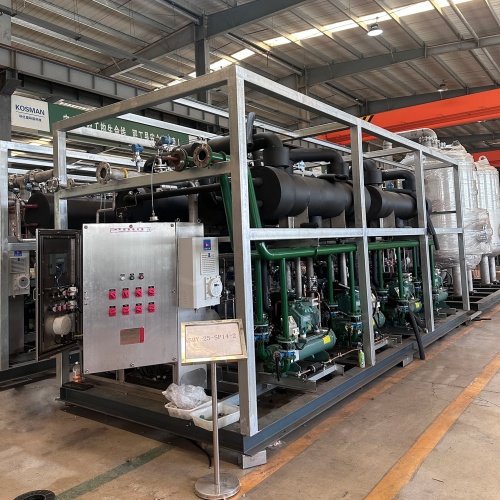

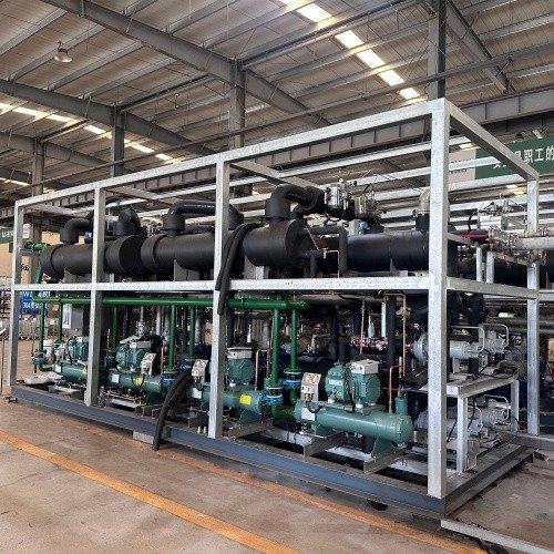
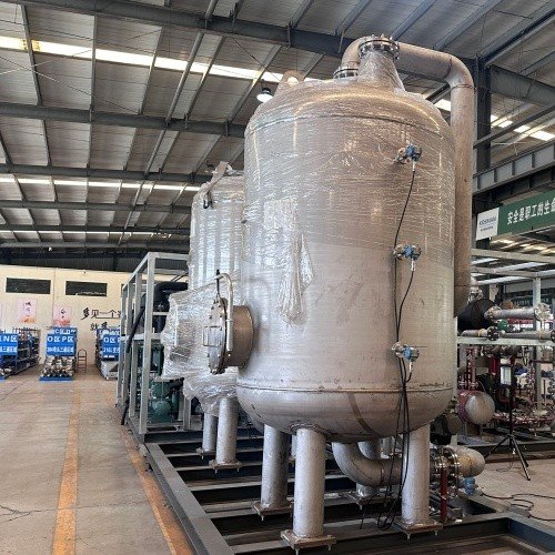
Shandong Kosman Environmental Technology Co., Ltd. is one of the leading manufacturers and suppliers of condensation adsorption oil vapor recovery device in China. Please feel free to buy premium equipment for sale here and get pricelist from our factory. All customized products are with high quality and low price.
I. Product Overview
The condensation-adsorption Vapor recovery unit is an integrated VOC (Volatile Organic Compound) treatment system that organically combines condensation and adsorption technologies. At the front end, the unit employs multi-stage condensation to liquefy and recover the majority of hydrocarbon components from high-concentration Vapor streams, enabling resource recovery. At the rear end, the remaining low-concentration tail gas undergoes deep purification via activated carbon adsorption to ensure ultra-low emissions. The condensation and adsorption systems are interlocked to ensure the stable operation of the entire system.
This product complies with national standards such as the *Emission Standard of Air Pollutants for Gas Stations* (GB 20952-2020), *Emission Standard of Air Pollutants for Oil Depots* (GB 20950), and *Technical Standard for Vapor Recovery and Treatment Facilities* (GB/T 50759-2022). It achieves a non-methane total hydrocarbon (NMTHC) removal rate of over 99% and emission concentrations as low as 80 mg/m³. It is widely used for stationary VOC emission sources, including gas stations, oil depots, refining and petrochemical enterprises, and chemical storage and transportation facilities.
II. Technical Principles and Process Flow
2.1 Core Technical Principles
The condensation-adsorption unit integrates the advantages of both adsorption and condensation methods, employing a "condensation-first, adsorption-second" staged treatment approach.
Stage 1 – Multi-stage Condensation: Utilizing the principle of varying vapor pressures of hydrocarbons at different temperatures, the unit progressively cools the Vapor stream through multiple refrigeration stages. Multi-component gases (comprising up to 90% of the stream) are cooled in stages to the dew point temperatures corresponding to their respective partial pressures, allowing different components to condense into liquid form and be recovered.
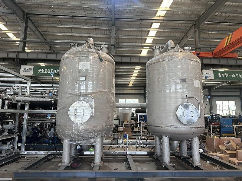
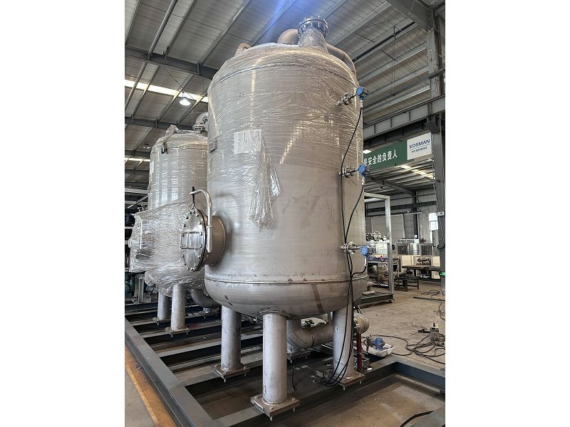
Stage 2 – Activated Carbon Adsorption: Tail gas discharged from the condensation unit is directed into the A and B tanks of the activated carbon adsorption system, which operate alternately. The adsorbent exhibits varying affinities for the components of the oil-gas/air mixture; hydrocarbon components are adsorbed onto the adsorbent surface, while the affinity for air is minimal, allowing the unadsorbed tail gas to be vented through the exhaust pipe.
2.2 Core Advantages of the Combined Process
The "condensation + adsorption" process combination integrates the advantages of both methods.
|
Comparison Criteria |
Pure Condensation Method |
Pure Adsorption Method |
Combined Condensation & Adsorption |
|
Energy Consumption |
Deep cryogenic condensation accounts for nearly 30% of total system energy use |
Moderate |
Significantly reduced total system energy consumption |
|
Safety |
Safe operation at low temperatures |
Adsorption heat effects pose safety risks |
High safety due to low-temperature processing of Vapor |
|
Footprint |
Small |
Large adsorption vessel volume |
Significantly reduced adsorption vessel volume |
|
Emission Concentration |
Requires deep cryogenic cooling to meet standards |
Tail gas emission concentration is controllable |
Ultra-low emissions |
|
Recovered Product |
Direct recovery of liquid oil products |
No direct recovery of liquid products |
Liquid oil recovery via condensation + deep purification via adsorption |
2.3 Typical Process Flow (Three-Stage Condensation + Dual-Tank Adsorption)
Vapor Collection: Hydrocarbon vapors volatilized during loading or storage are collected via sealed piping and conveyed to the treatment unit by an explosion-proof, variable-frequency fan.
Regenerative Pre-cooling: The vapors enter a regenerative heat exchanger, where they are cooled through heat exchange with the low-temperature gas exiting the condensation process.
Multi-stage Cascaded Condensation:
Stage 1 Pre-cooling (0–5°C): Cools the vapors to 0–5°C, removing most water vapor and components heavier than C9.
Stage 2 Shallow Cooling (-30°C to -40°C): Recovers nearly half of the hydrocarbons present in the vapors.
Stage 3 Intermediate Cooling (-60°C to -75°C): Recovers the vast majority of C3+ alkane components.
Stage 4 Deep Cooling (-110°C, optional): Ultra-low temperature deep condensation.
Gas-Liquid Separation and Recovery: Condensed liquid hydrocarbons are separated and recovered into storage tanks. C3+ alkanes are largely recovered via condensation, achieving a recovery rate of 80%–90%.
Adsorption-based Deep Purification: Uncondensed tail gas enters the activated carbon adsorption system (utilizing dual tanks, A and B, operating alternately). When one activated carbon unit reaches adsorption saturation, it switches to the desorption/regeneration phase, while the other unit begins operation.
Vacuum Desorption and Regeneration: Upon saturation, negative-pressure desorption is used to extract high-concentration vapors, which are returned to the upstream condensation unit. The desorption cycle is set to 15–20 minutes.
Compliant Discharge: Tail gas undergoes dual treatment (condensation followed by adsorption) and is discharged in compliance with emission standards.
III. System Composition
The condensation-adsorption hydrocarbon recovery unit primarily consists of the following core components:
|
System Module |
Key Equipment/Components |
|
Condensing System |
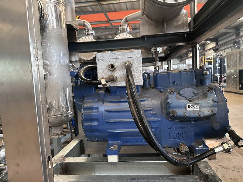
Refrigeration unit (compressor, condenser, expansion valve), cold box (multi-stage evaporator/heat exchanger) |
|
Adsorption System |
Adsorption vessels (dual vessels A & B), activated carbon adsorbent |
|
Desorption System |
Desorption vacuum pump, desorption piping |
|
Conveying System |
Oil transfer pump, explosion-proof variable-frequency fan |
|
Control System |
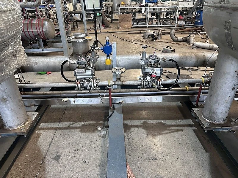
PLC (Programmable Logic Controller), explosion-proof instruments, touch screen |
|
Safety System |
Flame arrester, temperature sensor, pressure transmitter |
Depending on the cold source, they can be classified into two types-direct condensation and indirect condensation-suitable for different operating conditions.
IV. Technical Parameters
4.1 General Technical Parameters
|
Parameter Item |
Technical Specifications |
Notes |
|
Processing Capacity |
5–10,000 m³/h (customizable) |
Covers applications ranging from small gas stations to large petrochemical enterprises |
|
Condensing Temperature |
0°C → -30°C to -40°C → -60°C to -75°C → -110°C (optional) |
Three-stage or four-stage cascade condensation |
|
Condensation Recovery Rate |
80%–90% |
Primary recovery of C3+ alkanes via condensation |
|
Overall Recovery Rate |
≥97%–≥99% |
Combined condensation and adsorption process |
|
NMHC Removal Rate |
≥99% |
Far exceeds national standard requirements |
|
NMHC Emission Limit |
≤80 mg/m³ |
Superior to the national standard limit of 25 g/m³ |
|
Specific Energy Consumption |
≤0.25 kWh/Nm³ (three-stage condensation) |
|
|
Operating Power |
3–850 kW |
Depends on processing capacity |
|
Explosion-proof Rating |
Positive pressure type: Ex pxdmb IIB T4 / Flameproof type: Ex d IIB T4 |
|
|
Operating Noise Limit |
≤85 dB |
|
|
Control Method |
Fully automatic PLC control; supports remote monitoring |
|
|
Mean Time Between Failures (MTBF) |
≥6 months |
4.2 Processing Capacity Series
This unit offers a range of processing capacity specifications to meet application requirements of various scales:
|
Processing Capacity |
Applicable Scenarios |
|
5–30 m³/h |
Small gas stations |
|
100–300 m³/h |
Medium-sized gas stations, small oil depots |
|
400–800 m³/h |
Large oil depots, loading racks at refining and chemical plants |
|
1,000–2,500 m³/h |
Large petrochemical enterprises, terminals |
|
2,500–10,000 m³/h |
Ultra-large petrochemical projects |
V. Product Advantages and Features
5.1 High-Efficiency Recovery and Ultra-Low Emissions
High overall recovery rate: The condensation stage recovers 80%–90% of Vapor resources, while the adsorption stage provides deep purification of the remaining tail gas, resulting in an overall recovery rate of over 97%–99%.
Low emission concentration: Non-methane hydrocarbon (NMHC) emissions are limited to ≤80 mg/m³, far exceeding the national standard requirement of 25 g/m³.
Tangible results: Liquid oil products are recovered directly, and recovery volumes can be monitored in real time.
5.2 Significant Energy Savings and Consumption Reduction
Reduced energy consumption: To meet national emission standards using only the condensation method, deep cryogenic condensation is required, consuming nearly 30% of the system's total energy. Significantly Reduced Overall Energy Consumption via Combined Condensation & Adsorption Process
Cold Energy Recovery: Utilizes the cooling capacity from the downstream condensation stage (already cooled to a specific temperature) to pre-cool the incoming gas stream to 3–5°C, optimizing energy use for greater efficiency.
Low Specific Energy Consumption: The three-stage condensation recovery unit features a specific energy consumption of ≤0.25 kWh/Nm³.
5.3 Dual-Tank Alternation for Continuous Operation
24-Hour Uninterrupted Operation: Two adsorption tanks alternate between adsorption and desorption cycles, ensuring continuous system operation.
Automatic Switching: PLC automatically controls the switching sequence, eliminating the need for manual intervention.
Efficient Desorption: High-performance vacuum pump desorption ensures optimal cyclic operational efficiency.
5.4 Safe and Reliable Design
Low-Temperature Safety: The entire process operates under low-pressure and low-temperature conditions, minimizing fire risks.
Explosion-Proof Certification: Rated Ex d IIB T4 / Ex pxdmb IIB T4.
Optimized Adsorption Conditions: After condensing oil/gas vapors to -70°C, the residual gas consists of low-temperature air and low-concentration hydrocarbons; using adsorption tanks for enrichment improves adsorption conditions.
Extended Activated Carbon Lifespan: Low-temperature adsorption helps mitigate temperature rises caused by the heat of adsorption, thereby extending the service life of the activated carbon.
Reduced Adsorption Tank Volume: Condensation reduces the hydrocarbon content in the vapor stream, lowering the required amount of adsorbent and significantly reducing the size of the adsorption tanks.
5.5 Intelligent Control
Fully Automated PLC Control: Automates the entire process, including vapor collection, condensation/liquefaction, oil-water separation, and transfer of recovered condensate to storage.
Variable Frequency Regulation: Adjusts the refrigeration unit based on operating conditions to ensure economical system performance.
Remote Monitoring: Supports backend monitoring platforms and integration with enterprise DCS systems.
Interlock Control: Interlocked control between the condensation and adsorption systems ensures stable overall system operation.
5.6 Compact Structure and Easy Maintenance
Small Footprint: Adsorption tank volume is significantly reduced compared to systems designed for direct adsorption of high-temperature, high-concentration vapors.
Modular Design: Offers modular products that allow for flexible configuration combinations.
Low Maintenance Costs:Activated carbon operates under low loads with high adsorption efficiency and stable properties, ensuring long-term, reliable equipment operation.
VI. Application Scenarios
|
Application Area |
Specific Scenario |
Typical Substances Handled |
|
Oil Depots/Tank Farms |
Breathing losses from tank farms; vapor recovery during loading operations |
Gasoline, crude oil, fuel oil, etc. |
|
Gas Stations |
Stage III vapor recovery (treatment of storage tank vent emissions) |
Gasoline vapors |
|
Refining & Petrochemical Plants |
VOC control at loading racks and tank farms |
Light hydrocarbons, naphtha, etc. |
|
Chemical Enterprises |
Separation and recovery of chemical gases (e.g., benzene, methanol) |
Benzene, toluene, xylene, styrene, etc. |
|
Oilfields |
Associated gas recovery systems |
Light hydrocarbons, associated gas |
|
Terminals/Docks |
Vapor recovery during ship loading operations |
Refined petroleum products, chemicals |
|
Industrial Coating/Packaging & Printing |
Control of stationary VOC emission sources |
Organic solvent waste gas |
Applicable media for recovery:
Hydrocarbons: Gasoline, crude oil, fuel oil, kerosene, diesel, heavy oil, mixed hydrocarbons, etc.
Aromatics: Benzene, toluene, xylene, styrene, naphtha, etc.
Alcohols, ethers, ketones, and esters: Methanol, ethanol, acetone, ethyl acetate, etc.
Others: Light hydrocarbons, flare gas, carbon disulfide, dichloromethane, etc.
VII. Ordering Information
|
Item |
Details |
|
Product Name |
Condensation-Adsorption Oil & Gas Recovery Unit |
|
Process Options |
Condensation + Adsorption (3-stage/4-stage condensation + dual-tank alternating adsorption) |
|
Processing Capacity |
5–10,000 m³/h (customizable) |
|
Condensation Temperature |
0°C → -30°C to -40°C → -60°C to -75°C → -110°C (optional) |
|
Design Standards |
GB 20952-2020, GB/T 50759-2022 |
|
Explosion-proof Rating |
Ex d IIB T4 / Ex pxdmb IIB T4 |
|
Design Service Life |
≥10 years |
|
Warranty Period |
12–24 months |
|
Production Lead Time |
45–90 days (depending on capacity and process configuration) |
|
Optional Configurations |
Online monitoring system, DCS communication interface, 4G remote O&M module, dual-path anti-icing design |
Specific prices and delivery times are subject to actual quotation.
VIII. Contact Information
Please contact us for further product details, technical solutions, or to obtain a quote.
Hot Tags: condensation adsorption oil vapor recovery device, China condensation adsorption oil vapor recovery device manufacturers, suppliers, factory